


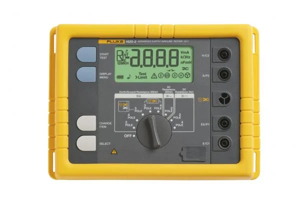
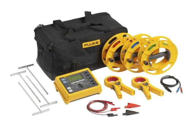
Fluke 1625-2 GEO Earth Ground Tester Kit
Key Features
The Fluke 1625-2 is a unique earth ground tester that can perform all four types of earth ground measurement:
- 3- and 4-Pole Fall-of-Potential (using stakes)
- 4-Pole Soil Resistivity testing (using stakes)
- Selective testing (using 1 clamp and stakes)
- Stakeless testing (using 2 clamps only) Adjustable limits - for quicker testing
- IP56 rated for outdoor use
- Rugged carrying case
- You can also perform earth ground tests in places you’ve not considered before: inside buildings, power pylons, or anywhere you don’t have access to soil
- The Fluke 1625-2 earth ground tester can measure earth ground loop resistances using only clamps
- With this test method, two clamps are placed around the earth ground rod and each are connected to the tester
- Automatic Frequency Control (AFC) - identifies existing interference and chooses a measurement frequency to minimize its effect, providing more accurate earth ground value
- R* measurement - calculates earth ground impedance at 55 Hz to more accurately reflect the earth ground resistance that a fault-to-earth ground would see
- Adjustable limits - for quicker testing
- 3- and 4-pole fall-of-potential, earth resistance loop testing
- 4-pole soil resistivity testing
- Selective earth ground rod testing using 1 clamp
- Stakeless earth ground rod testing using 2 clamps
- The 1625-2 offers internal memory storage of up to 1500 records
- Accessible via USB port for rapid data transfer and viewing of results
- This earth ground tester also gives you world-class accessories that take the tedium out of earth ground testing
- Heavy-duty stakes can be hammered into dry, hard soil.
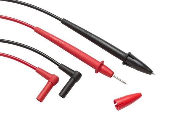
- New color-coded wires make setup simple and help eliminate mistakes and speed up setup and tear down time as much as 50%
- IP56 rated for outdoor use
- Rugged carrying case
Product overview: Fluke 1625-2 GEO Earth Ground Tester Kit
The Most Complete Stakeless Earth Ground Tester
The Fluke 1630-2 FC Stakeless Earth Ground Clamp is the kind of high-quality, rugged tool you expect from Fluke. Heavy-duty clamp jaw stays in alignment and in calibration even in every day, on-the-job industrial environments. Test the grounding components of equipment in hard-to-reach spaces, including areas that are indoors or fully paved and do not permit driving auxiliary test stakes. Stay online—identify ground loop resistance without the need to disconnect then reconnect the earth electrode from the system.
Stakeless earth ground measurement testing
The Fluke 1625-2 improves your earth ground testing process with:
The Fluke 1625-2 gives you versatility in earth ground testing
The Fluke 1625-2 offers you simpler, faster earth ground tests than ever before
Additional tool features
Specifications: Fluke 1625-2 GEO Earth Ground Tester Kit
| General Specifications | |||||
| Memory | Internal memory storage up to 1500 records accessible via USB port | ||||
| Measuring function | Interference voltage and frequency, earthing resistance 3- and 4-pole with/without clip-on current transformer, resistance 2-pole with AC, 2- and 4-pole with DC | ||||
| Display | 4 digit (2999 Digit) - 7 segment liquid crystal display, with improved visibility | ||||
| Operation | Central rotary switch and function keys | ||||
| Temperature Range | |||||
| Operating temperature | -10°C to 50°C (14°F to 122°F) | ||||
| Storage temperature | -30°C to 60°C (-22°F to 140°F) | ||||
| Temperature coefficient | ±0.1% of reading/°C < 18°C > 28°C | ||||
| Type of protection | IP56 for case, IP40 for battery door according to EN60529 | ||||
| Max voltage | Warning – socket "clamp" to socket E, ES, S or H | ||||
| Urms = 0 V | |||||
| Sockets E, ES, S or H to each other in any combination, max. Urms = 250 V (pertains to misuse) | |||||
| Safety | Protection by double and/or reinforced insulation. Max. 50 V to earth per IEC61010-1. Pollution degree 2 | ||||
| Quality standard | Developed, designed and manufactured to comply with DIN ISO 9001 | ||||
| External field influence | Complies with DIN 43780 (8/76) | ||||
| Auxiliary power | 6 x 1.5 V alkaline (IEC LR6 or type AA) | ||||
| Battery life span | With IEC LR6/type AA: typ. 3,000 measurements (RE+RH ≤ 1 kΩ) | ||||
| With IEC LR6/type AA: typ. 6,000 measurements (RE + RH > 10 kΩ) | |||||
| Dimensions (W x H x D) | 250 x 133 x 187 mm (9.75 x 5.25 x 7.35 in) | ||||
| Weight | ≤ 1.1 kg (2.43 lb) without accessories 7.6 kg (16.8 lb) incl. accessories and batteries in carrying case | ||||
| Case material | Polyester | ||||
| Measurement of Interference Voltage DC + AC (UST) | |||||
| Measuring limits of error: method | Full wave rectification | ||||
| Measuring range | 1 V to 50 V | ||||
| Display range | 0.0 V to 50 V | ||||
| Resolution | 0.1 V | ||||
| Frequency range | DC/AC 45 Hz to 400 Hz sine | ||||
| Accuracy | ±(5% of rdg + 5 digit) | ||||
| Measuring sequence | Approx. 4 measurements/s | ||||
| Internal resistance | Approx. 1.5 MΩ | ||||
| Max. overload | Urms = 250 V | ||||
| Measurement of Interference Frequency (F) | |||||
| Measuring limits of error: method | Measurement of oscillation period of the interference voltage | ||||
| Measuring range | 6.0 Hz to 400 Hz | ||||
| Display range | 16.0 Hz to 299.9 Hz to 999 Hz | ||||
| Resolution | 0.1 Hz to 1 Hz | ||||
| Range | 1 V to 50 V | ||||
| Accuracy | ±(1% of rdg + 2 digit) | ||||
| Earthing Resistance (RE) | |||||
| Measuring method | Current and voltage measurement with probe as IEC61557-5 | ||||
| Open circuit voltage | 20/48 V, AC | ||||
| Short circuit current | 250 mA AC | ||||
| Measuring frequency | 94, 105, 111, 128 Hz selected manually or automatic. (AFC) 55 Hz in function R1 | ||||
| Noise rejection | 120 dB (16 2/3 , 50 , 60, 400 Hz) | ||||
| Max. overload | Urms = 250 V | ||||
| Electrical Measurement Specifications | |||||
| Intrinsic Error or Influence Quantity | Reference Conditions or Specified Operating Range | Designation Code | Requirements or Test in Accordance with the Relevant Parts of IEC 1557 | Type of Test | |
| Intrinsic error | Reference conditions | A | Part 5, 6.1 | R | |
| Position | Reference position ±90° | E1 | Part 1, 4.2 | R | |
| Supply voltage | At the limits stated by the manufacturer | E2 | Part 1, 4.2, 4.3 | R | |
| Temperature | 0°C and 35°C | E3 | Part 1, 4.2 | T | |
| Series interference voltage | See 4.2 and 4.3 | E4 | Part 5, 4.2, 4.3 | T | |
| Resistance of the probes and auxiliary earth electrodes | 0 to 100 x RA but ≤ 50 kΩ | E5 | Part 5, 4.3 | T | |
| System frequency | 99% to 101% of the nominal frequency | E7 | Part 5, 4.3 | T | |
| System voltage | 85% to 110% of the nominal voltage | E8 | Part 5, 4.3 | T | |
| Operating error | B = ±(|A| + 1,15 √E21 E22 E23 E24 E25 E26 ) | Part 5, 4.3 | R | ||
| B[%] = ± B/fiducial value x 100% A = intrinsic error En = variations R = routine test T = type test | |||||
| Measuring range | 0.020 Ω to 300 kΩ | ||||
| Display range | 0.001 Ω to 2.999 Ω | ||||
| 3.00 Ω to 29.99 Ω | |||||
| 30.0 Ω to 299.9 Ω | |||||
| 0.300 kΩ to 2.999 kΩ | |||||
| 3.00 kΩ to 29.99 kΩ | |||||
| 30.0 kΩ to 299.9 kΩ | |||||
| Resolution | 0.001 Ω | ||||
| 0.01 Ω | |||||
| 0.1 Ω | |||||
| 1 Ω | |||||
| 10 Ω | |||||
| 100 Ω | |||||
| Accuracy | ±(2% of rdg + 2 digit) | ||||
| Operating error | ±(5% of rdg + 5 digit) | ||||
| Measuring time | Typical 8 seconds with a fixed frequency 30 sec. max. with AFC and complete cycle of all measuring frequencies | ||||
| Additional error because of probe-and auxiliary earth electrode resistance | RH(RS + 2000 Ω)/RE x 1.25 x 10⁻⁶% + 5 digits | ||||
| Measuring error of RH and RS | Typ. 10% of RE + RS + RH | ||||
| Max. probe resistance | ≤ 1 MΩ | ||||
| Max. auxiliary earth electrode resistance | ≤ 1 MΩ | ||||
| Automatic check if error is kept within the limits required by IEC61557-5. If after a measurement of probe-, auxiliary earth electrode- and earthing resistance, a measurement error of higher than 30% is assumed because of the influencing conditions, the display shows a warning symbol and a notice that RS or RH are too high. | |||||
| Automatic Switchover of Measuring Resolution in Dependence to Auxiliary Earth Electrode Resistance RH | |||||
| RH with Umeas = 48 V | < 300 Ω | ||||
| < 6 Ω | |||||
| < 60 Ω | |||||
| < 600 Ω | |||||
| RH with Umeas = 20 V | < 250 Ω | ||||
| < 2.5 kΩ | |||||
| < 25 kΩ | |||||
| < 250 kΩ | |||||
| Resolution | 1 mΩ | ||||
| 10 mΩ | |||||
| 100 mΩ | |||||
| 1 Ω | |||||
| Selective Measurement of the Earthing Resistance (RE Clamp) | |||||
| Measuring method | Current and voltage measurement with probe as per EN61557-5 and current measurement in the individual branch with additional current transformer (patent applied for). | ||||
| Open circuit voltage | 20/48 V AC | ||||
| Short circuit current | 250 mA AC | ||||
| Measuring frequency | 94, 105, 111, 128 Hz selected manually or automatically (AFC), 55 Hz (R1) | ||||
| Noise rejection | 120 dB (162/3, 50, 60, 400 Hz) | ||||
| Max. overload | Max. Urms = 250 V (measurement will not be started) | ||||
| Measuring range | 0.020 Ω to 300 kΩ | ||||
| Display range | 0.001 Ω to 2.999 Ω | ||||
| 3.00 Ω to 29.99 Ω | |||||
| 30.0 Ω to 299.9 Ω | |||||
| 0.300 kΩ to 2.999 kΩ | |||||
| 3.00 kΩ to 29.99 kΩ | |||||
| Resolution | 0.001 Ω | ||||
| 0.01 Ω | |||||
| 0.1 Ω | |||||
| 1 Ω | |||||
| 10 Ω | |||||
| Accuracy | ±(7% of rdg + 2 digit) | ||||
| Operating error | ±(10% of rdg + 5 digit) | ||||
| Additional error because of probe- and auxiliary earth typ. electrode resistance | RH(RS + 2000 Ω)/RETOTAL x 1.25 x 10⁻⁶% + 5 digits | ||||
| Measuring error of RH and RS | Typ. of 10% of RETOTAL + RS + RH | ||||
| Measuring time | Typ. 8 sec. with a fixed frequency 30 sec. max. with AFC and complete cycle of all measuring frequencies. | ||||
| Minimal current in single branch to be measured | 0.5 mA | With transformer (1000:1) | |||
| 0.1 mA | With transformer (200:1) | ||||
| Max. interference current through transformer | 3 A | With transformer (1000:1) | |||
| 1. With recommended current clamps/transformers. | |||||
| Resistance Measurement (R~) | |||||
| Measuring method | Current and voltage measurement | ||||
| Measuring voltage | 20 V AC, square pulse | ||||
| Short circuit current | > 250 mA AC | ||||
| Measuring frequency | 94, 105, 111, 128 Hz selected manually or automatically (AFC) | ||||
| Measuring range | 0.020 Ω to 300 kΩ | ||||
| Display range | 0.001 Ω to 2.999 Ω | ||||
| 3.00 Ω to 29.99 Ω | |||||
| 30.0 Ω to 299.9 Ω | |||||
| 300 Ω to 2999 Ω | |||||
| 3.00 kΩ to 29.99 kΩ | |||||
| 30.0 kΩ to 299.9 kΩ | |||||
| Resolution | 0.001 Ω | ||||
| 0.01 Ω | |||||
| 0.1 Ω | |||||
| 1 Ω | |||||
| 10 Ω | |||||
| 100 Ω | |||||
| Accuracy | ±(2% of rdg + 2 digit) | ||||
| Operating error | ±(5% of rdg + 5 digit) | ||||
| Measuring time | Typical 6 seconds | ||||
| Max. interference voltage | 24 V, with higher voltages measurement will not be started | ||||
| Max overload | Urms max. = 250 V | ||||
| Resistance Measurement (R DC) | |||||
| Measuring method | Current- voltage measurement as per IEC61557-4 possible | ||||
| Measuring voltage | 20 V DC | ||||
| Short circuit current | 250 mA DC | ||||
| Formation of measured value | With 4-pole measurement wires on H, S, ES can be extended without additional error. Resistances > 1 Ω in wire E can cause additional error of 5m Ω/Ω. | ||||
| Measuring range | 0.020 Ω to 300 kΩ | ||||
| Display range | 0.001 Ω to 2.999 Ω | ||||
| 3.00 Ω to 29.99 Ω | |||||
| 30.0 Ω to 299.9 Ω | |||||
| 300 Ω to 2999 Ω | |||||
| 3.0 kΩ to 29.99 kΩ | |||||
| 30.0 kΩ to 299.9 kΩ | |||||
| Resolution | 0.001 Ω | ||||
| 0.01 Ω | |||||
| 0.1 Ω | |||||
| 1 Ω | |||||
| 10 Ω | |||||
| 100 Ω | |||||
| Accuracy | ±(2% of rdg + 2 digit) | ||||
| Operating error | ±(5% of rdg + 5 digit) | ||||
| Measuring sequence | Approx. 2 measurements/s | ||||
| Measuring time | Typical 4 second including reversal of polarity (2-pole or 4-pole) | ||||
| Maximum interference voltage | ≤ 3 V AC or DC, with higher voltages measurement will not be started | ||||
| Maximum inductivity | 2 Henry | ||||
| Maximum overload | Urms = 250 V | ||||
| Compensation of Lead Resistance (RK) | |||||
| Compensation of lead resistance (RK) can be switched on in functions RE 3-pole, RE 4-pole (clamp), R AC, and R DC 2-pole | |||||
| Formation of measured value | Rdisplay = Rmeasured - Rcompensated2 | ||||
| 2. Value of setpoint entry RK = 0.000 Ω, variable from 0.000 to 29.99 Ω by means of measuring adjustment. | |||||
| Stakeless Ground Loop Measurement (Two Clamp Stakeless) | |||||
| Switch position | RA 4-pole (two clamp Stakeless) | ||||
| Resolution | 0.001 Ω to 0.1 Ω | ||||
| Measuring range | 0.02 Ω to 199.9 Ω | ||||
| Accuracy | ±(7% rdg + 3 digit) | ||||
| Operating error | ±(10% rdg + 5 digit) | ||||
| Measuring voltage | Vm = 48 V AC (primary) | ||||
| Measuring frequency | 128 Hz | ||||
| Noise current (IEXT) | Max. IEXT = 10 A (AC) (RA < 20 Ω) | ||||
| Max. IEXT = 2 A (AC) (RA > 20 Ω) | |||||
| Measuring principle: Stakeless measurement of resistance in closed loops using two current transformers. Automatic range selection. The information regarding stakeless ground loop measurements is only valid when used in conjunction with the recommended current clamps at the minimum distance specified. | |||||
Models: Fluke 1625-2 GEO Earth Ground Tester Kit
Fluke 1625-2 Kit
Fluke 1625-2 GEO Earth Ground Tester Kit
Includes:
- GEO Earth Ground Tester
- User’s Manual
- Batteries
- Quick Reference Guide
- USB Cable
- 2 Clamps
- C1620 Professional Carrying Case
- 4 Earth Ground Stakes
- 3 Cable Reels
Resources: Fluke 1625-2 GEO Earth Ground Tester Kit
Manuals (6)
1623-2 | Users Manual
1623-2 | Users manual supplement
1625-2 | Users Manual
1625-2 | Users manual supplement
1623-2/1625-2 | Statement of memory volatility
1623-2/1625-2 | Quick reference guide
Accessories: Fluke 1625-2 GEO Earth Ground Tester Kit
Test leads, probes and clips (1)
Fluke ES-162P3-2 3-Pole Stake Kit
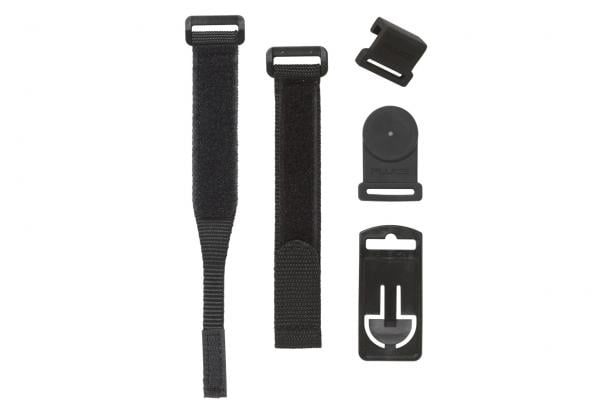
Magnetic hangers, utility tools (1)
Fluke ES-162P4-2 4-Pole Stake Kit
Adapters and cables (3)
Fluke Cable Reel 25M BL
Fluke Cable Reel 25M GR
Fluke Cable Reel 50M RD
Current clamps and probes (1)
Fluke EI-1623 Selective/Stakeless Clamp Set
Other (1)
Fluke EI-162BN 320 mm Diameter Split Core Transformer